In the evolving landscape of energy storage, supercapacitors (also known as ultracapacitors or electrochemical capacitors) have emerged as a pivotal technology. They bridge the gap between conventional electrolytic capacitors—which offer high power but low energy—and rechargeable batteries, which provide high energy but limited power delivery speeds.
Whether you are an engineer designing a backup power system or a hobbyist working on a high-pulse application, understanding how to manage these devices is crucial.
1. How They Work: The Two Faces of Storage#
Unlike traditional capacitors that use a solid dielectric, supercapacitors primarily rely on two storage principles:
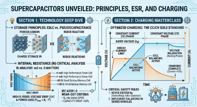
- Electric Double-Layer Capacitance (EDLC): This is a non-Faradaic (physical) process where charges are stored electrostatically at the interface between the electrode and the electrolyte. Because no chemical bonds are broken, EDLCs can withstand up to 1 million charge-discharge cycles.
- Pseudocapacitance: This involves fast, reversible Faradaic redox reactions (chemical charge transfer) on the electrode surface. This mechanism can increase capacitance by a factor of 10 to 100 compared to pure EDLCs.
For high-performance needs, Hybrid Capacitors (like Lithium-ion capacitors) combine both principles to achieve significantly higher energy densities while maintaining fast charging capabilities.
2. The Internal Resistance (ESR) Debate: Is “0.5” Normal?#
A common question among users is whether an internal resistance of 0.5 is acceptable. The answer depends entirely on the unit and the application.
Units Matter#
- For large power-type supercapacitors (100F to 10,000F), an internal resistance ($R_i$) of 0.5 mΩ (milliohms) is an excellent, high-performance value.
- However, if the value is 0.5 Ω (500 mΩ), it might be normal for a small memory-backup capacitor but would indicate a failure in a high-power module.
The Risks of High Resistance#
Excessive resistance leads to significant voltage drops ($\Delta V$) and internal heat generation, calculated as:
$$P_{loss} = R_i \cdot I^2$$End-of-Life Criteria#
According to international standards (IEC 62391-2), a supercapacitor is considered to have reached its “wear-out” stage when:
- Its internal resistance exceeds four times its initial datasheet specification.
- Its capacitance drops by more than 30%.
3. Charging Mastery: Safe and Efficient Methods#
Charging a supercapacitor is not as simple as connecting it to a battery. Because of their extremely low ESR, they can draw massive inrush currents that might damage your power supply.
The CC/CV Gold Standard#
The most reliable method is the Constant Current / Constant Voltage (CC/CV) approach:
- Constant Current (CC) Phase: Limit the current to the manufacturer’s recommended level to avoid overheating and surge damage.
- Constant Voltage (CV) Phase: Once the capacitor reaches its Rated Voltage ($U_R$), the power supply maintains that voltage while the current naturally tapers off.
Critical Safety Rules#
- Never Exceed Rated Voltage: Supercapacitors are low-voltage devices (typically 2.1V to 3.0V per cell). Exceeding this limit causes electrolyte decomposition, gas formation (hydrogen), and potential cell rupture.
- Implement Balancing: When connecting cells in series to achieve higher voltages, you must use active or passive balancing circuits. This ensures no single cell is pushed into an overvoltage state due to minor differences in capacitance or leakage current.
- Account for Voltage Relaxation: After disconnecting the charger, you may see the voltage drop slightly. This is not necessarily a leak; it is a physical phenomenon called voltage relaxation, caused by ions diffusing deeper into the porous carbon electrodes.
Summary#
Supercapacitors offer an incredible combination of high power, long cycle life, and rapid charging. By respecting their voltage limits, monitoring internal resistance trends, and using proper CC/CV charging techniques with balancing, you can ensure your energy storage system remains safe and reliable for years to come.