In the modern landscape of energy storage, Supercapacitors (also known as ultracapacitors or electrochemical capacitors) have become core components in regenerative braking, UPS systems, and pulse power applications. Their appeal lies in a cycle life reaching hundreds of thousands or even millions of cycles, paired with a power density that far exceeds traditional batteries.
However, to unlock their full performance and ensure safety, one must understand their unique electrochemical characteristics.
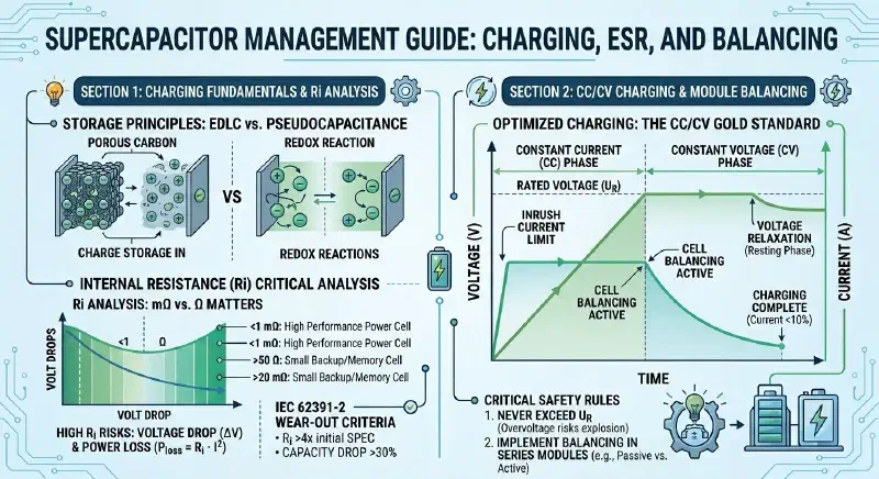
I. Precision Charging: The CC/CV Mode and “Voltage Control” Core#
Charging a supercapacitor differs fundamentally from standard electrolytic capacitors. Due to their extremely low Equivalent Series Resistance (ESR), they generate massive inrush currents at the initial moment of charging. For the proper CV/CC charging procedure, follow our step-by-step guide.
- Recommended Charging Mode (CC/CV): Industry standards typically utilize Constant Current / Constant Voltage charging.
- Constant Current (CC) Phase: Limits the initial current to prevent excessive thermal and electromagnetic stress from damaging the internal connections between the capacitor elements and collectors.
- Constant Voltage (CV) Phase: Once the voltage reaches the Rated Voltage ($U_R$), the voltage is held steady while the current tapers off exponentially.
- Strict Voltage Limits: Supercapacitors are low-voltage components. Rated voltages usually fall between 2.1V and 2.7V (though Lithium-ion capacitors can reach 3.8V). Exceeding these limits causes electrolyte decomposition (producing hydrogen gas), leading to leakage, swelling, or internal short circuits.
- Voltage Relaxation: After charging stops, the voltage may drift toward previous levels due to ion diffusion deep within the porous electrodes. This Voltage Relaxation is a normal physical process and does not indicate a leak.
II. Debunking the “0.5 ESR” Myth: Units and Lifespan Standards#
To judge whether internal resistance is normal, one must clarify the measurement standard (AC ESR at 1kHz is significantly lower than DC internal resistance, $R_i$) and the units involved.
- Standard ESR Values: For high-power capacitors above 100F, an internal resistance below 1 milliohm (mΩ) is an excellent metric; if “0.5” refers to 0.5mΩ, performance is superior. However, small backup capacitors (0.1F - 470F) typically have values around 20mΩ. If the unit is Ohms (Ω), a value of 0.5Ω is catastrophic for power applications.
- Failure Criteria (The 4x/30% Rule): According to the IEC/EN 62391-2 standard, a supercapacitor is considered to have reached “wear-out failure” when:
- Its capacitance drops by more than 30%.
- Its internal resistance increases to more than 4 times the initial datasheet specification.
- Thermal Management: Heat loss during charging is proportional to the square of the current ($P_{loss} = R_i \cdot I^2$). Excessive internal resistance causes intense heating during charge/discharge cycles, significantly shortening service life.
III. Module Balancing: The “Commander” of System Stability#
When multiple cells are connected in series to achieve higher voltages (e.g., more than 3 cells or a total voltage > 8V), a Balancing Board is an indispensable safety barrier.
- The Inevitability of Imbalance: Due to manufacturing tolerances, small differences exist in capacitance and leakage current among cells. Series charging naturally leads to uneven voltage distribution.
- Balancing Solutions:
- Passive Balancing: Uses parallel resistors to dissipate excess energy. It is low-cost but involves heat loss.
- Active Balancing: Utilizes electronic voltage management to redistribute current in real-time. It is highly efficient and suitable for precision scenarios with high cycling requirements.
- Safety Barrier: Balancing boards effectively prevent individual cells from premature overvoltage failure. In extreme cases, they prevent a cell that discharges first from suffering reverse voltage damage.
IV. Storage and Application Recommendations#
- Environmental Constraints: Supercapacitors are highly sensitive to temperature; higher core temperatures accelerate electrolyte evaporation. Follow the “10-degree rule”: for every 10°C decrease in operating temperature, the expected lifespan doubles.
- Polarity Awareness: While symmetrical supercapacitors lack inherent polarity, it is advised to maintain the polarity established during production. For Hybrid and Asymmetric capacitors (like Lithium-ion capacitors), reverse connection is strictly prohibited and will cause permanent damage.
Summary#
A supercapacitor is not just a high-performance energy storage device; it is a precision electronic component. By strictly adhering to CC/CV charging specifications, monitoring ESR trends, and configuring appropriate balancing circuitry, you can ensure your system remains efficient and safe throughout a service life that can exceed a decade.